Testing electrical polarity correctly starts with examining cable color codes and markings for phase, neutral, and ground identification. You’ll need to use continuity testing with a multimeter on de-energized circuits, listening for confirmation beeps across test points. For live systems, employ GS38-approved test lamps to verify Line-to-Neutral and Line-to-Earth connections, ensuring no voltage appears between Neutral and Earth. Digital multimeters provide precise voltage and polarity readings when you connect leads properly. Command these fundamentals to access advanced transformer testing techniques.
TLDR
- Always ensure circuits are de-energized before testing polarity to prevent electrical shock and equipment damage.
- Use a digital multimeter with red lead on positive terminal and black lead on negative terminal for accurate polarity identification.
- For transformer polarity testing, measure primary voltage, secondary voltage, and combined voltage to determine additive or subtractive polarity.
- Verify proper conductor identification using visual inspection of cable markings and standard color coding before polarity testing.
- Test energized systems only with GS38-approved equipment, checking Line-to-Neutral first, then Line-to-Earth for proper grounding verification.
Visual Inspection Techniques for Cable Color Code Verification

Before you reach for any testing equipment, visual inspection of cable color codes provides your first and most accessible method for verifying polarity in electrical systems.
Start by examining the cable’s outer sheath markings to identify which standard applies—IEC, NEC, or CEC—since each uses different color schemes for phase, neutral, and ground conductors. This visual identification becomes crucial for maintenance and troubleshooting scenarios where understanding the correct wire functions can save significant time and prevent potential safety hazards. Additionally, having knowledge of winter survival skills can aid in ensuring safety during electrical work in cold environments.
Continuity Testing Methods for Circuit Conductor Connections
Once you’ve completed your visual inspection of cable color codes, continuity testing becomes your next essential step for verifying proper circuit conductor connections and identifying potential wiring faults.
Set your multimeter to continuity mode and guarantee the circuit’s powered off completely. Connect test leads firmly across points you’re examining, listening for the confirming beep that indicates a complete electrical path. For enhanced sensitivity when testing large cable networks, consider using circuits with high-gain transistors that can detect continuity with just a few millivolts, eliminating the need for lengthy test probes. Additionally, ensure your equipment is suitable for sea kayak fishing essentials to maintain safety and comfort during the testing process.
Live Testing Procedures Using Test Lamps and Meggers

While continuity testing verifies connections in de-energized circuits, live testing procedures allow you to confirm polarity in energized systems using specialized equipment like GS38-approved test lamps and megger instruments. You’ll test Line-to-Neutral first for full illumination, then Line-to-Earth for proper grounding. No voltage should appear between Neutral and Earth, indicating correct wiring and safe operation. Proper grounding is crucial for portable generators to ensure safety during testing and prevent hazardous situations.
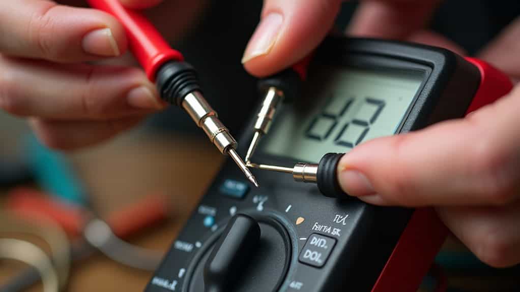
Digital Multimeter Applications for Voltage and Polarity Confirmation
Digital multimeters offer electricians a precise and versatile method for confirming voltage levels and polarity in both DC and AC circuits, building upon the foundational testing covered with test lamps and meggers.
You’ll connect the black lead to your negative terminal and red to positive, then observe the display for accurate polarity confirmation. Additionally, having a well-stocked first aid kit ensures that you are prepared for any electrical accidents that may occur during testing.
Transformer Polarity Testing and Special Circuit Considerations

Testing transformer polarity requires a different approach than standard voltage measurements, as you’ll need to determine the phase relationship between primary and secondary windings to guarantee safe operation.
Connect voltmeters across primary (Va), secondary (Vb), and between windings (Vc). If Vc equals Va minus Vb, you’ve got subtractive polarity; if Va plus Vb, it’s additive polarity.
Final Note
You’ve now learned multiple approaches to verify polarity correctly, from basic visual inspections to advanced digital testing methods. Remember, you’ll achieve the most reliable results by combining these techniques rather than relying on just one method. Always prioritize safety by de-energizing circuits when possible, and don’t hesitate to use multiple verification steps. With practice, you’ll develop confidence in selecting the right testing approach for each specific electrical situation you encounter.