First, disconnect all power sources from your trolling motor for safety, then verify your transducer cable length and plan the routing path. Remove the back half and four screws from the shaft-mount bracket, positioning the transducer 3-7 inches from the propeller with a slight 2-degree downward tilt. Secure with appropriately-sized stainless steel clamps, ensuring the transducer points straight down for accurate sonar readings. Test performance gradually at increasing speeds, and the following steps will optimize your installation.
TLDR
- Disconnect all power sources from the trolling motor and remove battery connections before beginning installation.
- Position the transducer 3-7 inches forward of the propeller with a slight 2-degree downward tilt.
- Use shaft-mount or barrel-mount brackets with appropriate screws and rubber liners based on shaft diameter.
- Ensure the transducer faces straight down perpendicular to the water surface for accurate sonar readings.
- Test installation with transducer fully submerged, gradually increasing speed to check for signal skipping issues.
Safety Preparations and Power Disconnection
Before you begin mounting your transducer, you’ll need to prioritize safety by completely disconnecting all power sources from your trolling motor.
Remove battery connections or unplug power cables entirely, ensuring no residual power remains in the circuits.
Implement lockout/tagout procedures where applicable, and avoid working in wet conditions to prevent electrical hazards during installation. Additionally, ensure proper ventilation while using any tools that may emit fumes to maintain a safe workspace.
Cable Length Verification and Routing Planning
Once you’ve secured your workspace and disconnected power, you’ll need to verify your transducer cable length and plan its routing path carefully.
Most trolling motor transducers include 15-foot cables, though some extend to 25 feet. Measure your planned route from the transducer mount to your chartplotter before installation, ensuring adequate length while avoiding electrical interference sources. Additionally, consider the importance of high-resolution displays for improving readability during your fishing trips.
If your installation requires additional reach beyond the standard cable length, extension cables are available to bridge the gap between your transducer and fish finder unit.
Transducer Mount Assembly and Component Setup
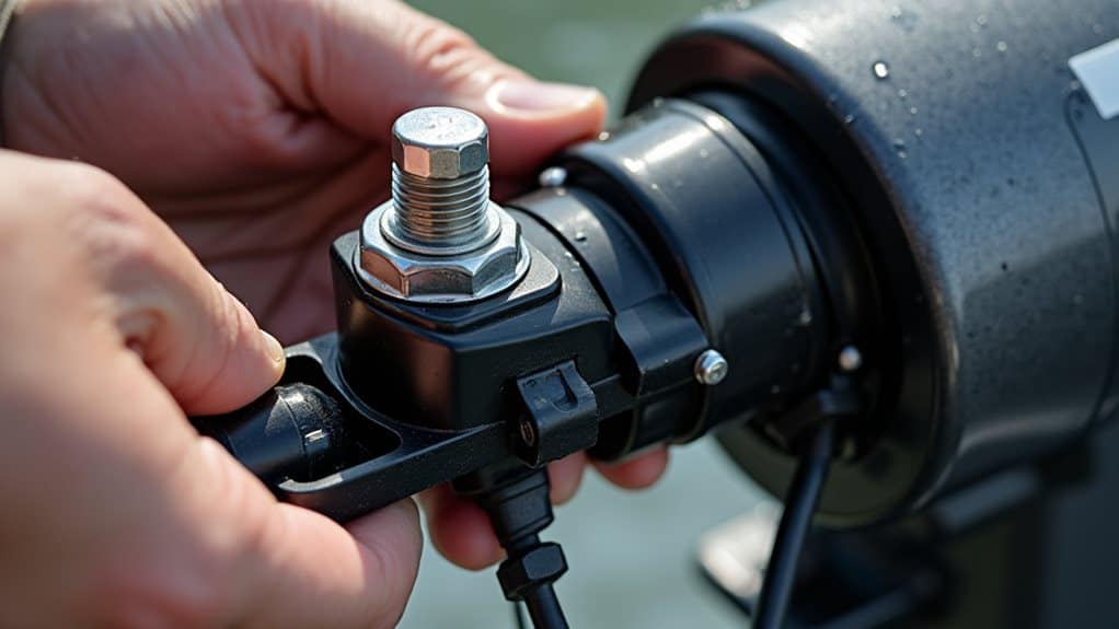
Two primary mounting options are available for attaching your transducer to a trolling motor: shaft-mount brackets and barrel-mount systems. Sea Kayak Fishing Essentials also recommend using a fish finder for better navigation and fishing success.
Before assembly, remove the back half and four screws from your shaft-mount bracket’s parts bag. Additionally, locate the front half of the shaft mount bracket from the same parts bag and identify the arrow orientation for correct attachment positioning.
For shafts larger than 42mm diameter, you’ll need alternate screws.
Insert rubber liners for shafts 25mm or smaller.
Optimal Mounting Location Selection
You’ll need to carefully consider three critical positioning factors when selecting where to mount your transducer on the trolling motor shaft.
The distance from the propeller directly affects signal clarity and prevents interference, while the downward angle guarantees ideal sonar beam coverage of the bottom structure.
Additionally, positioning the transducer correctly relative to your boat’s direction of travel minimizes turbulence and maximizes the accuracy of your depth readings. Understanding sonar beam coverage is essential for ensuring optimal performance and effective fish detection.
Distance From Propeller
The single most critical factor in achieving clear sonar readings from your trolling motor-mounted transducer is maintaining proper distance from the propeller.
You’ll need to keep at least 3 to 7 inches of clearance between your transducer and propeller to avoid turbulence and interference.
Position it forward of the propeller where water flow remains smooth and undisturbed.
Downward Angle Positioning
Achieving ideal sonar performance requires careful attention to your transducer’s downward angle positioning, which directly affects how well you’ll detect fish and bottom structure beneath your boat.
A slight downward tilt of approximately 2 degrees compensates for your boat’s bow-up attitude while underway, keeping the sonar beam parallel to the bottom for accurate readings.
Direction of Travel
Once you’ve established the proper downward angle, selecting the ideal mounting location becomes essential for maximizing your sonar’s effectiveness during travel and fishing activities.
Position your transducer to align with your primary fishing zone and expected travel direction. If you’re casting from the bow, you’ll benefit from real-time sonar feedback directly below your angling position.
Proper Transducer Orientation and Angle Positioning
Getting your transducer’s orientation and angle just right is essential for accurate sonar readings and preventing costly damage to your equipment.
You’ll need to position the transducer so it points straight down into the water, maintain the ideal beam angle for clear bottom readings, and keep it safely away from your trolling motor’s propeller wash.
These three factors work together to guarantee you get reliable depth information while protecting your investment from interference and physical damage.
Downward Pointing Position
Proper transducer orientation forms the foundation of successful sonar performance, and the downward pointing position guarantees you’ll receive the clearest possible readings from your fish finder.
You must position the transducer perpendicular to the water surface, ensuring the narrow notch faces away from the propeller to avoid turbulence and interference that compromises signal clarity.
Optimal Beam Angle
Several crucial factors determine how effectively your transducer’s sonar beam penetrates the water and delivers accurate readings, with beam angle positioning serving as the most critical element for best fish finder performance.
You’ll need to align your transducer perpendicular to the water’s surface, ensuring the sonar cone maintains proper coverage while avoiding signal distortion from incorrect mounting angles.
Propeller Interference Avoidance
While achieving ideal beam angle sets the foundation for quality sonar readings, positioning your transducer to avoid propeller interference represents an equally critical challenge that can make or break your fish finder’s performance.
You’ll need to mount your transducer forward of the propeller, away from turbulent wash areas that create acoustic distortion and signal disruption.
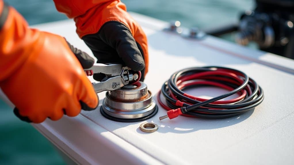
Hose Clamp Installation and Securing Methods
Installing a hose clamp correctly forms the foundation of a secure transducer mount, and selecting the right materials makes all the difference in long-term performance.
Choose stainless steel clamps sized appropriately for your trolling motor shaft. Position the clamp so your transducer aligns with the motor’s centerline, avoiding propeller interference.
Tighten firmly without over-stressing components.
Cable Routing Through Motor Housing
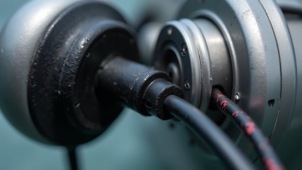
Proper cable routing through your trolling motor housing requires careful attention to three critical areas: the entry point, the path through internal components, and the exit location.
Use existing pass-through holes with grommets to maintain waterproofing.
Route cables away from electrical components and motors, keeping exposure minimal.
Leave adequate slack for adjustments while avoiding tight coils near power cables.
Cable Protection and Management Techniques
Once you’ve successfully routed your transducer cable through the motor housing, protecting it from damage becomes your next priority.
Apply high-strength poly tubing around cables to prevent abrasion from motor movement. Use zip ties to create secure anchor points without over-tightening, which can damage internal shielding.
Maintain separation from power cables to reduce electromagnetic interference and preserve signal clarity.
Performance Testing and Alignment Verification
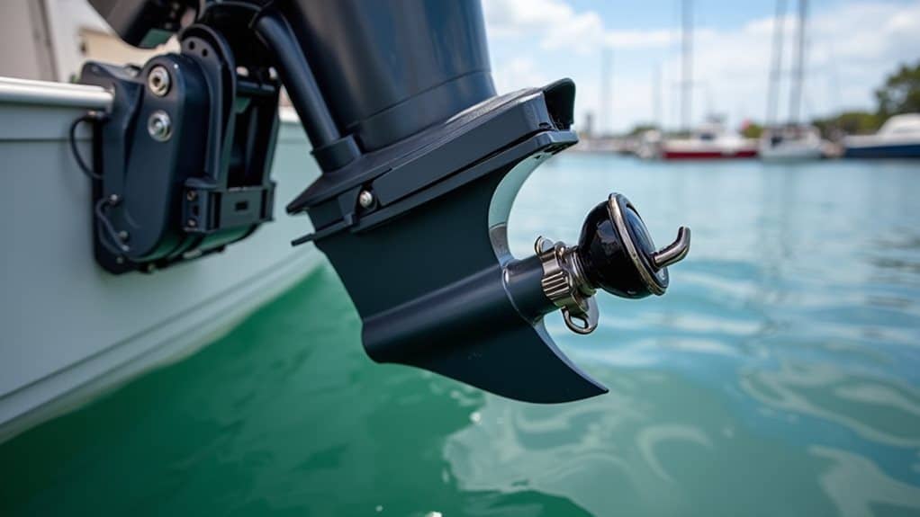
After completing the cable management process, you’ll need to verify that your transducer installation delivers peak performance across all operating conditions.
Start testing with your boat in water, ensuring the transducer is fully submerged for proper signal transmission.
Gradually increase boat speed to identify any sonar skipping issues that indicate alignment problems requiring adjustment.
Maintenance Inspection and Long-Term Care
Successful installation and testing represent just the beginning of your transducer’s operational life, and establishing a regular maintenance routine will protect your investment while ensuring consistent sonar performance for years to come.
Inspect the housing, mounting bracket, and cables regularly for damage, corrosion, or looseness that could compromise signal accuracy and reliability.
Final Note
You’ve now equipped yourself with the essential knowledge to mount your transducer correctly on your trolling motor. Remember, proper cable routing and secure mounting prevent costly damage while ensuring peak sonar performance. Take your time during installation, double-check all connections, and don’t skip the testing phase. With regular maintenance inspections and careful handling, your transducer will provide years of reliable fish-finding capability on the water.


