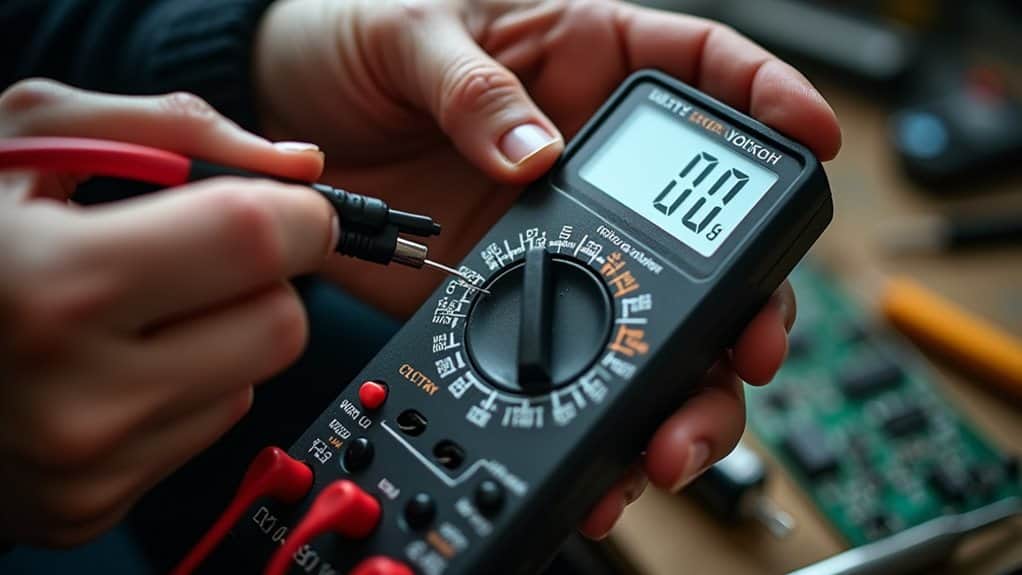
You’ll need a multimeter to check polarity: set it to DC voltage mode, connect the black probe to COM and red to VΩ, then touch the probes to your circuit. A positive reading confirms correct polarity, while a negative reading indicates reversed connections. This matters because incorrect polarity can destroy sensitive components like diodes and capacitors, create serious shock hazards, and even render safety devices like GFCIs ineffective. Understanding the fundamentals and testing techniques guarantees your electrical work remains safe and functional.
TLDR
- Polarity defines electrical charge orientation (positive/negative); reversed connections block proper electron flow and can damage polarity-sensitive components like diodes and capacitors.
- Incorrect polarity creates serious safety hazards including electrical shock, arc flash incidents reaching 35,000°F, and rendered safety devices like GFCIs.
- Use a multimeter in DC voltage mode: positive reading confirms correct polarity, while negative reading indicates reversed connections.
- Visual inspections check color-coded wiring (red=positive, black=negative) and component markings like +/-, bands, or LED lead lengths.
- Specialized testing methods include continuity testing with ohmmeters and injection techniques for transformers to verify proper polarity configuration.
Understanding Polarity in Electrical and Electronic Systems
When working with electrical and electronic systems, understanding polarity is fundamental to ensuring your circuits function correctly and safely.
Polarity defines the orientation of electrical charges, distinguishing positive and negative terminals in your circuits.
Electrons flow from the negative pole, where electron density is higher, to the positive pole.
This directional flow is marked visually with plus (+) and minus (-) symbols, alongside color coding—red for positive, black for negative.
Reversing these connections can prevent your device from operating, as incorrect polarity blocks the intended electron flow through the circuit.
Smart chargers include temperature compensation to protect batteries and improve charging safety.
The Critical Role of Polarity in Safety and Device Protection
Because polarity determines the directional flow of electrical current through your circuits, getting it wrong doesn’t just mean your device won’t work—it creates serious safety hazards and can destroy expensive equipment.
Reversed polarity increases your risk of electrical shock, can trigger arc flash incidents, and renders safety devices like GFCIs ineffective. Arc flash incidents can reach temperatures up to 35,000°F, approximately four times hotter than the surface of the sun. You’ll also damage polarity-sensitive components including diodes and capacitors, shortening device lifespan considerably. Using the wrong fuel type for appliances can create comparable risks to improper electrical polarity, including appliance damage and increased safety hazards.
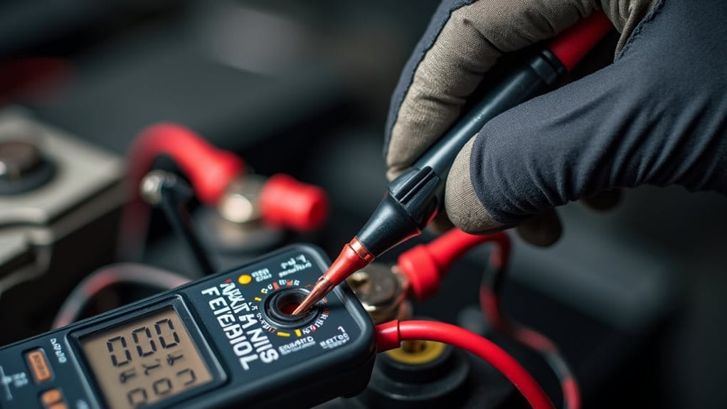
Polarity Testing Methods for AC and DC Circuits
Understanding the safety risks associated with incorrect polarity naturally leads to the question of how you actually verify it in your electrical systems.
You’ll find several practical approaches available, ranging from simple visual inspections using color-coded wiring standards to more technical methods like continuity testing with low-resistance ohmmeters.
For transformers and current transformers, specialized injection techniques using devices like the CPC 100 provide accurate verification through primary or secondary signal testing.
Additionally, when working with devices such as an RV air conditioner, checking components like the start capacitor can help identify faults that may be related to polarity or power-supply issues.
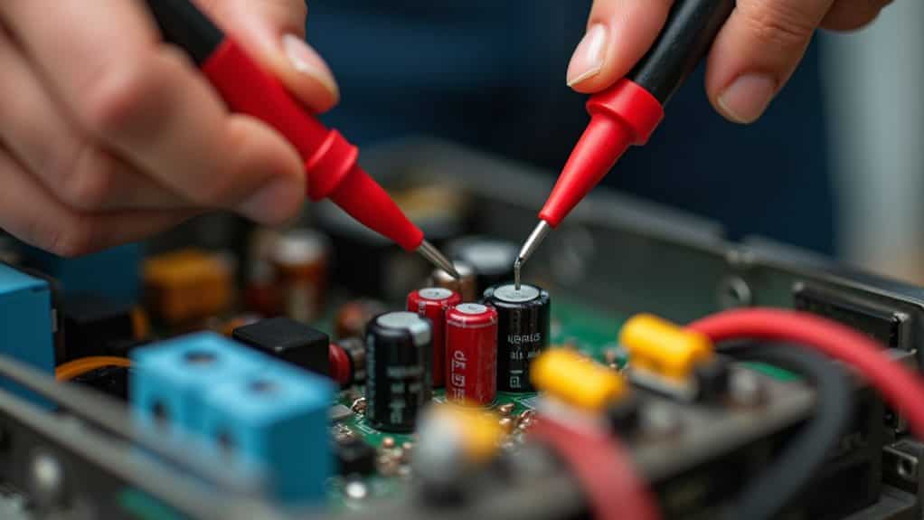
Verifying Component Polarity in Electronic Devices
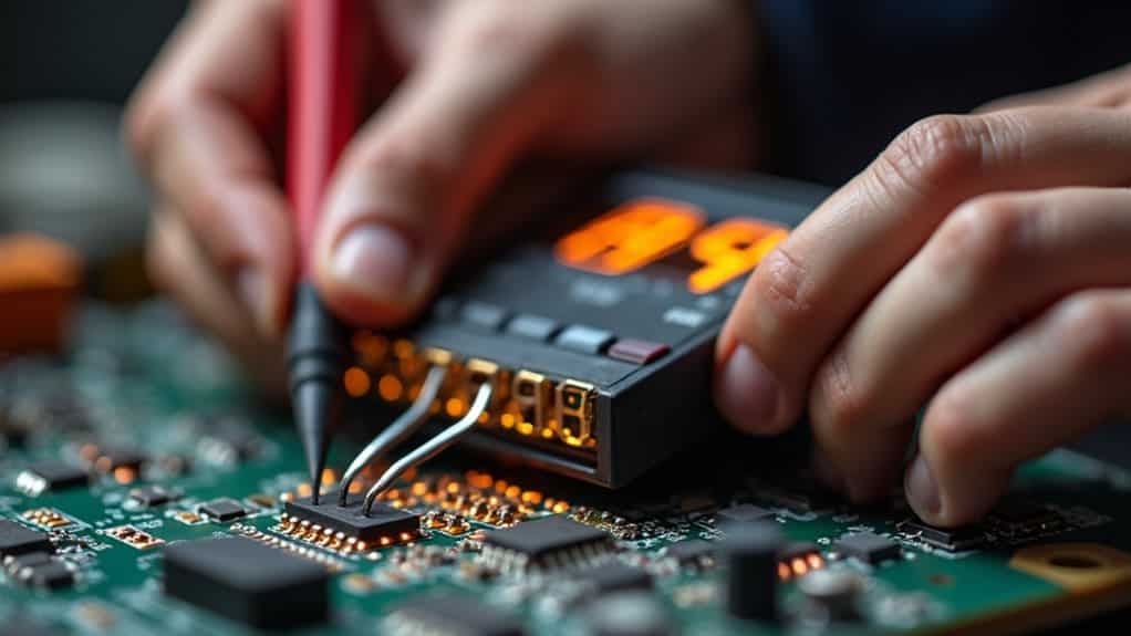
Building on the testing methods used for AC and DC circuits, verifying polarity in individual electronic components requires a more detailed, hands-on approach that focuses on physical markings and component-specific indicators.
You’ll find most polarized components display visible polarity marks—”+” and “-” symbols, colored bands, or stripes. For LEDs, look for the longer lead (anode/positive) or flat edge (cathode/negative). Multi-pin ICs mark pin one for proper orientation. When in doubt, consult the manufacturer’s datasheet for component markings and correct polarity information.
Using Multimeters and Test Equipment to Confirm Polarity
Once you’ve identified the physical markers on your components, a multimeter becomes your most reliable tool for confirming polarity with precision.
Set it to DC voltage mode, connect the black probe to COM and red to VΩ, then touch them to your circuit’s negative and positive points respectively.
A positive reading confirms correct polarity, while a negative number indicates reversed connections.
Common Polarity Mistakes and How to Avoid Them
While identifying polarity correctly is essential, even experienced electricians occasionally make wiring mistakes that can compromise safety and functionality.
Reversed polarity, where hot and neutral wires are swapped, creates serious shock hazards by keeping devices energized when switched off.
You’ll also encounter loose connections from counterclockwise wire hooks, improper strip lengths exposing bare conductors, and misconnected GFCI terminals that eliminate ground-fault protection entirely.
Final Note
You’ve now learned the essential methods for checking polarity and understand why it’s vital for safety and equipment longevity. Remember to always verify polarity before connecting devices, use your multimeter correctly, and pay attention to color codes and markings. These simple precautions prevent short circuits, component damage, and potential hazards. When you’re uncertain about polarity, take a moment to test—it’s far easier than replacing damaged equipment or addressing safety issues later.